Latest News
27Mar
Radical wiring (again)
Last night I managed to get the air compressor to run for the first time; it was providing a 12V feed to the relay via the pressure switch, so when the air pressure is low the pump is started. The relays were wired with a 12V feed and expecting a low signal (0v) to operate, so for the air compressor relay only, I've swapped the 12V feed for an earth, and now the pump runs and is under the control of the pressure switch.I wired in the 3 way DTM plugs on to the 12V NPN speed sensors, and couldnt get them to work. There didnt appear to be any supply voltage. I found a wire in the loom, labelled "Sensor power" which I traced back to the plugs, and sure enough it made a circuit. The question then was what voltage do we provide them with. The S100 needs a 5V pk-pk signal from the wheel speed sensors, and when I tried supplying 5V, none of the sensors detected motion from the wheels. Hmm, could they require 12V? Would that harm the inputs on the ECU? I asked Alex Chard (DTA) and he confirmed that running the sensors at 12V, and providing 12V to the wheel speed sensors, wouldn't be an issue. So I will wire the feed wire up to 12V and the ECU will hopefully be able to see the rotation of the wheels.
We then ran the engine for a few seconds, to check that the electric water pump was running under ECU control (it was) and that it was pumping water in the correct direction (it was). One last job was to fit the rain light, but when I was stripping the insulation back from the 12V wire to the light, the wire pulled out from the potting compound in the back of the light unit. When I got home I removed the potting compound from around the wires, and soldered two new wires on, and I just need to add some epoxy or black sikaflex back to the hole I made to ensure that the connections are water proof.
The final job was to check the paddles work, now we had air pressure, and configure the ECU for the 1-N-2-3-4-5-6 gear sequence from the bike box. That was quite easy, and then we struggled to find where the gear position voltages are set, for every gear. It wasnt in sensor linearisation, instead it was in Shift Cut. Once that was programmed in, the ECU showed the correct gear on the dashboard :D
25Mar
Repairs nearing completion
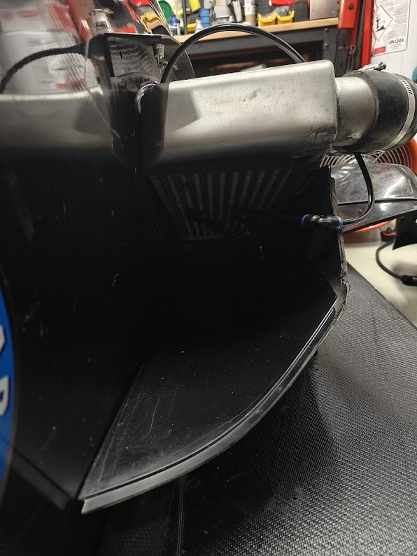
Last night I repaired the broken corner on the front bodywork where the nose cone attaches to the body. I mixed some resin to bond the pieces togeteher, but as ever, its too cold for it to cure in the quoted 60 minutes, so I'll give it 24 hours and see what its like tonight. I also fitted the aero section back in to the intercooler side pod, which for some reason I'd never refitted after swapping to the larger intercooler. It fits well, just needs a slight trim along one edge, so I'll get that done and refit the cowling tonight.The Plex dashboard is on its way from Greece. I am expecting it to replace the ECUMaster CAN switch board that sits on the back of the steering wheel, and relays the paddles and rotary switch positions back to the ECU. The Plex has plenty of digital and analogue inputs, and should be able to present the switch status rapidly enough for the ecu not to miss a paddle switch change. I'll set the polling frequency to the same as how it's setup in the CAN switch board.
24Mar
DTM plugs ordered
I've had to order another set of DTM connectors for the Radical SR3 wiring loom, with 20AWG pins, to connect to the four leads that take the signals from the wheel speed sensors to the ECU. They should be with me for Thursday, hopefully sooner so I can complete the job one evening after work.The link to the Youtube short showing the engine running is here
22Mar
The Hyabusa Engine runs
Another trip over to work on the Radical today, and after swapping the fuse box for a version with 12 fuses, then loading the calibration which I'd modifed using the cal supplied by Alex Chard of DTA, we filled the dry sump tank with oil, and with the spark plugs removed and injectors unplugged, primed the system until it produced 1.5bar of oil pressure on the key; we then went for an engine run, and with some manual throttle, it started on the first push of the button and ticked over smoothly. Oil pressure was 6bar, and there were no issues.I then wired in the rectifier output (with 25A inline fuse) across the battery, so it would charge the battery when the engine was running. I also wired in a switch on the dashboard to cut the power to the ignition circuit, which allows the engine to be stopped without losing power to the ECU. I wired in the air compressor too, so ready to be tested. The IGN switch tested out ok on the next run, as did the charging circuitry.
I'm very happy its worked so well, and all I need to do next is to wire in the wheel speed sensors, and make some more changes to the dashboard to hook up the few remaining switches which are used for launch and traction control. I need to check the water pump runs too, as thats on Aux6 and it wasnt enabled by default as the previous owner of the ECU didnt run an electric pump. Its a shame the ECU doesnt drive the pump using PWM, as it will be on all the time, rather than running at a slower rate when the engine is ticking over.
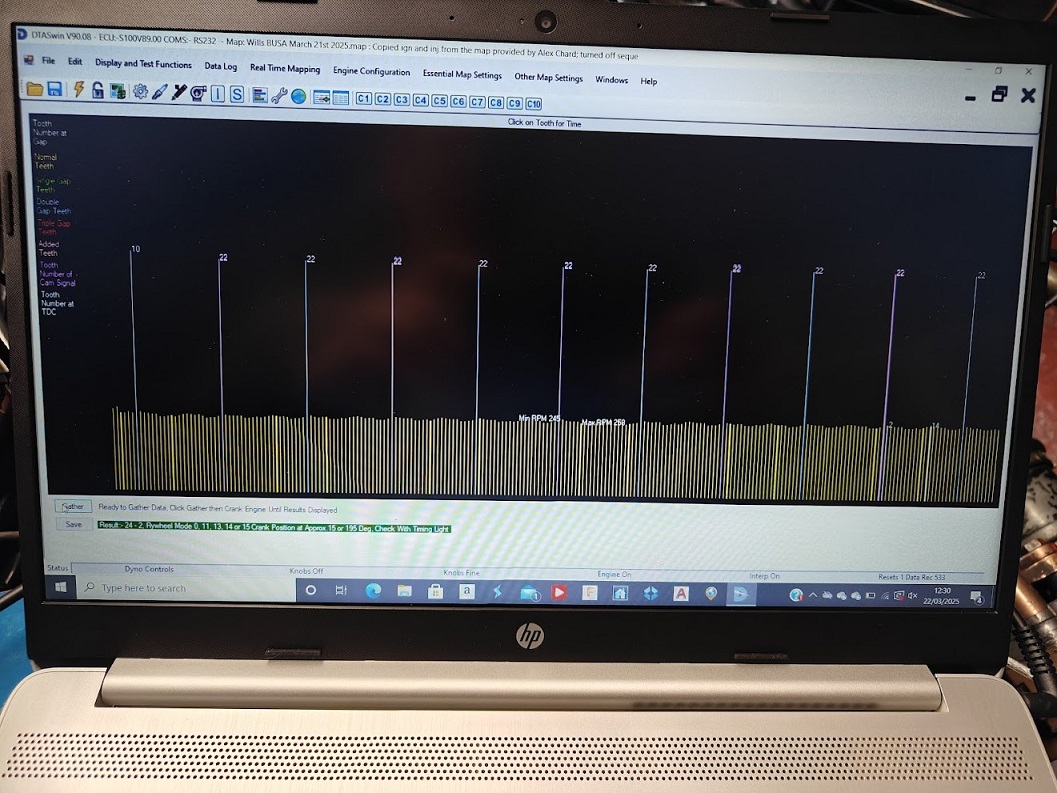
This is the scope output from the DTA SWIN software, showing the pulses received from the magnetic crank sensor, with the engine spun over on the starter motor. Nice and clean.
18Mar
Lambda connected
I wired in the Innovate LC2 wideband controller tonight, and used the Yellow (Analogue output 1) wire to pin 19 on the ECU. This is the wideband output. The ECU was then configured to use the Innovate LM1 sensor, and it showed a rising AFR which topped out at Lambda 1.5, which is quite normal when the engine isnt running. I also wired in a launch control button, which for some reason the ECU couldnt see, so I need to investigate where on the ECU the pin goes back to to work out why its not being seen. We are changing the fuse box from a 6 fuse to a 12 fuse version, as we've already run out of fuses for the different circuits. I've ordered a 12 way rotary switch and 470R resistors, so I can build a traction control switch for the front panel. If the parts arrive tomorrow I'll build it up for fitting on Saturday.17Mar
DTA map updated
The ECU in the Radical came from a car running a 2.0 Zetec, so the ignition and fuel tables all needed modifying. Alex from DTA kindly provided a map for a Gen 1 Busa, so I copied over the fuel and ignition tables last night, and set the number of teeth on the crank sensor wheel to 24 with 2 missing. I've also setup the Lambda parameters to use the Innovate LM1/LC1, and setup things like the RPM range (0-10500), Engine Start Fuelling tables, etc, and I've turned off sequential injection and sequential ignition until we have got the engine running, and then they'll be tried.16Mar
Another day of wiring on the Radical
On Saturday I connected up all the relays to the DTA ECU on the Radical SR3, and the ECU can now control the radiator fan, water and fuel pumps. We performed tests on all the outputs and everything worked fine. I rescaled the water temp sensor to Suzuki K5 and it now reads the correct temperature. I ran in to difficulties figuring out the wiring to the 5 wire Bosch LSU4.9 Lambda, so I left it alone, and checking today with Alex at DTAFast, it transpires we have bought a wideband sensor, and the DTA S100 doesnt work with wideband (I should have remembered as I had an S80 on the Fiesta with the LC1 wideband controller) so we've had to order the Innovate LC2 wideband controller, which will drive the five wire wideband sensor, and provide the ECU with a linear signal showing the Oxygen content of the exhaust. The older 4 wire narrow band sensors only provide a lean/rich signal, so thats a good reason for going for the wideband version. Another issue was the connector on the new engine oil temperature sensor, which was meant to be a mini-timer but was a totally different oval/rounded 2 pin connector, so thats going back and will be swapped for the mini-timer version. So all thats left to do is to connect the lambda, and run wires from the switches on the dashboard to the inputs on the ECU for the launch control, traction control and wet/dry map settings, as well as a switch for the rain light. I ran a pair of wires to the microswitch we're fitting on the clutch pedal, which will allow first or reverse to be selected as long as the clutch pedal is depressed first. Oh and the wheel speed sensors need plumbing in, which is another very straight forward job.When we went to fit the 73mm printed wheel speed sensor rings to the output cups, we realised we couldnt slide them on because there is a raised lip/section to the end of the cups, which would have required a larger diameter than 73mm to slide them over. So we cut both the rings using a thin blade hack saw, slid them on, and used sikaflex to bond the rings on securely. In the mean time I have redesigned the rings to allow them to be slid over the end of the cup, and then locked in position using an M2.5mm x 5mm socket head screw.
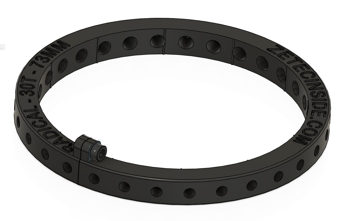
I've sent off the bezel and two different front panels for 3D printing, as well as the Mk2 73mm rings, delivery should be in two weeks time. Meanwhile, there is still no sign of the seat from Triple M, or the fresh Pirelli tyres, and my first event at Blyton is on April 13th...
14Mar
Plex steering wheel bezel re-designed... again...
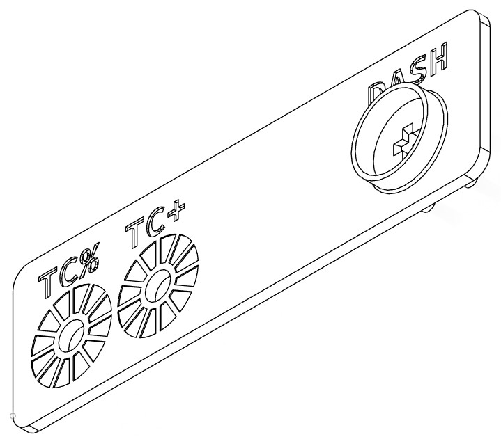
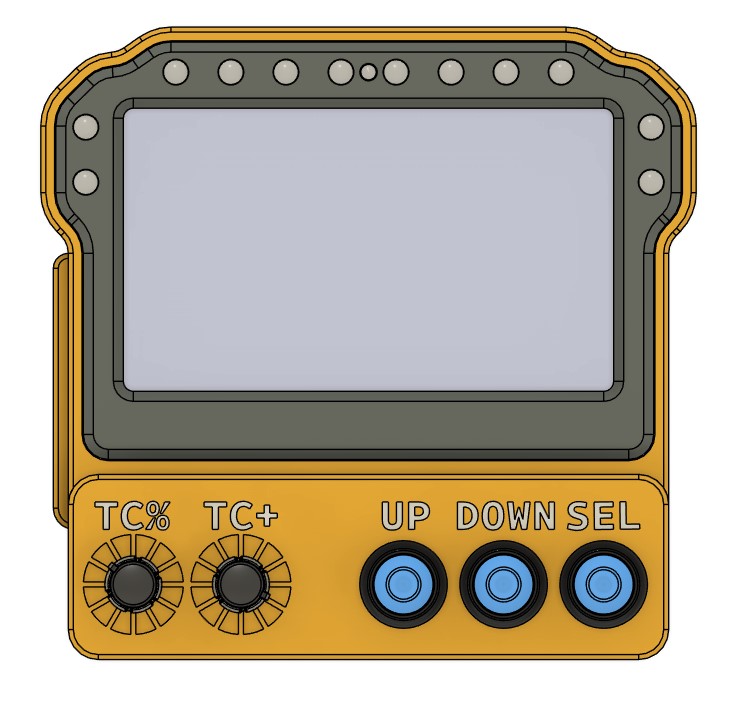
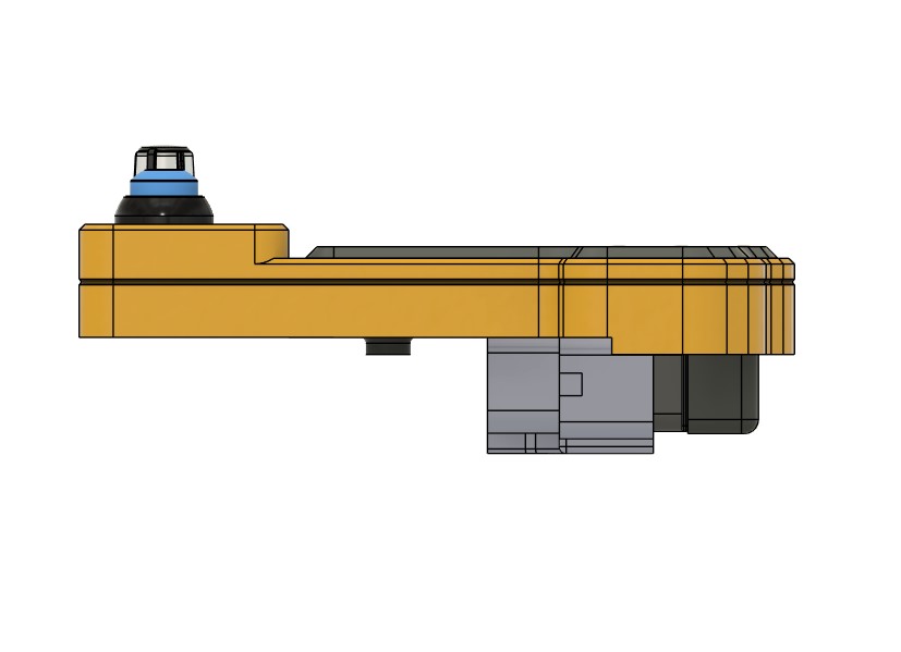
I've made the bezel more versatile by allowing for the front switch panel to be interchangeable. This will allow me to change the switch layout and print a small panel which will then fit in to the front of the bezel. I think now I have finished the design, finally, unless I suddenly think of anything else.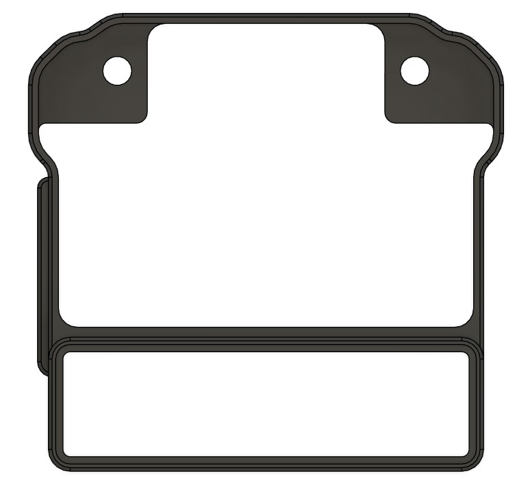

13Mar
Plex steering wheel bezel re-designed...
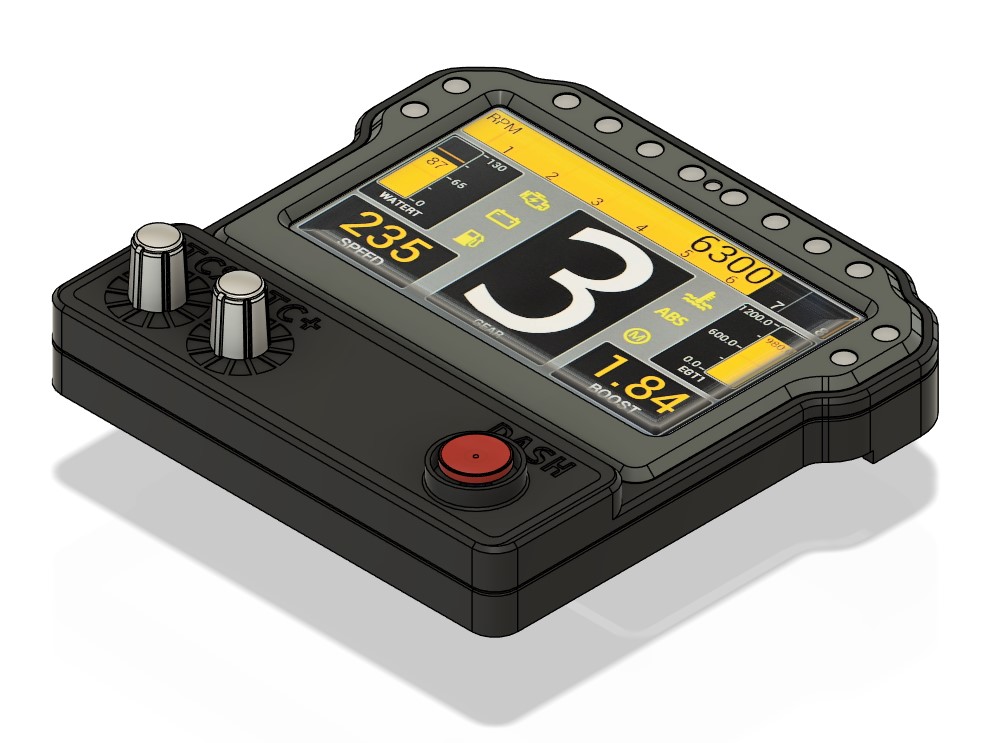
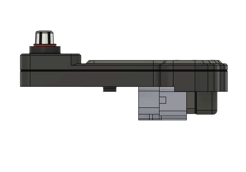
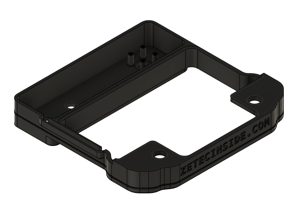
I found a 5 way hat switch that I'm going to use instead of the three buttons, for navigating the screens on the Plex dash. This will allow Up, Down and Back navigation, and when the switch is pressed down, that will provide the Select signal. I've redrawn the panel that fits in the front of the bezel, and I may print it seperately to the bezel, which will allow me to replace the panel if I decide to redesign it for additional switches.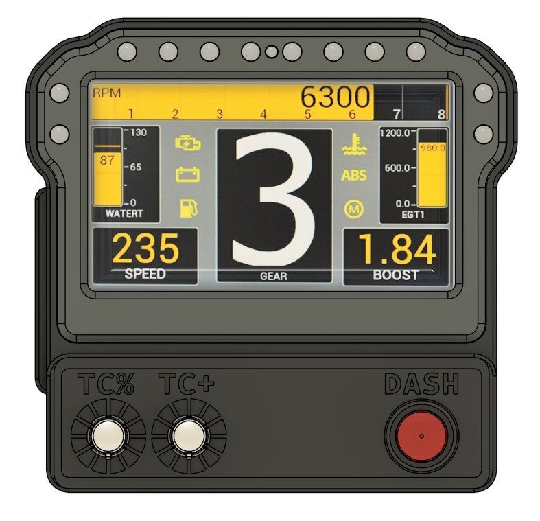
10Mar
Plex steering wheel bezel designed...
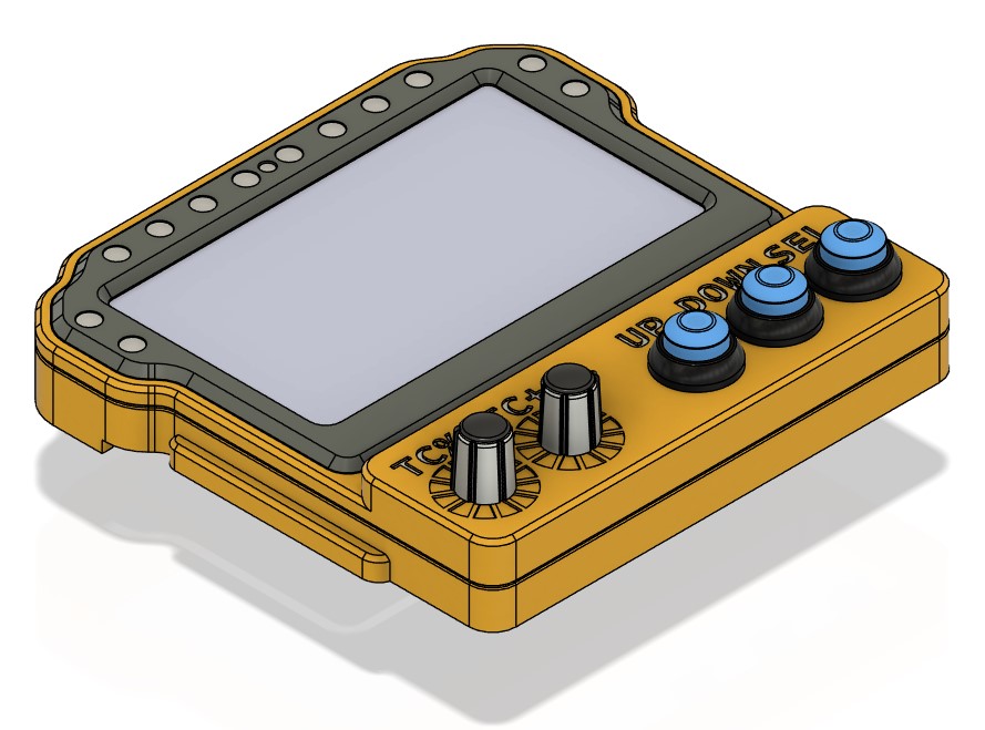
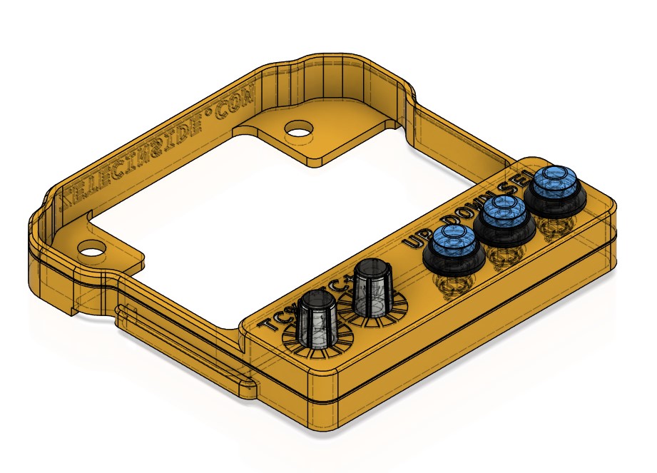
This took a few hours to put together. The bezel attaches to the Plex SDM-330 which itself is bolted to the steering wheel. I'm on the lookout for a rugged hat switch to allow me to replace the three buttons that operate the display options. My son's Walksnail FPV head set has the very thing, on the side, which allows the menus to be navigated, and options selected by pushing the button down. Thats exactly what I need, and I'm now on the hunt for one.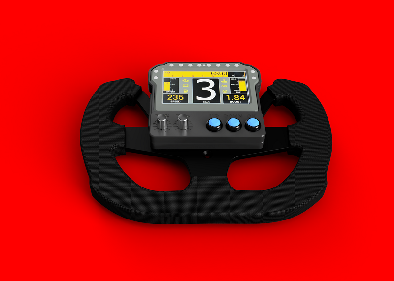
This is how it should look fitted to the wheel. Excuse the crappy drawing of the wheel, the real thing is far more attractive LOL
9Mar
Day 3 of wiring on the Radical
On Saturday I continued with the wiring on the Radical. I added an air temperature sensor, gearbox oil temperature, and wired in the water pump, radiator fan, and the fuel pump. I also swapped the pins around for the fuel injectors to match the same firing order as the COP's. I powered the dashboard up too, to see if the CAN data from the ECU was being received, and it was :DThe relay block is now fixed in place, and I ran out of locking 6.3mm spade terminals which prevented me from connecting up the fan and both pumps, but that should be completed next weekend. For some reason the Busa engine coolant temp sensor is reading 87C at ambient, but I think that could be down to the sensor scaling, so I'll see if the sensor is working and try to recalibrate the ECU for it.
I ran the engine today for the first time since it was switched off in June after the crash. I needn't have worried. First push of the button and it started. No horrible noises, no drama, and very little smoke from the exhaust. I ran it for 15 minutes to let everything warm up. The link to a Youtube short of her running is here VIDEO
1Mar
Day 2 of wiring on the Radical
On Saturday I spent another day working on the wiring loom on the Radical. I now have the 3 wire cam sensor connected to the DTA S100 ECU, as well as the fuel pressure sensor, and the gear position sensor. I also swapped the connections over for the COPs, so they fire in the correct order.The BUSA Gen2 engine has a firing order of 1243, so
COP1 goes to Pin 10
COP2 goes to Pin 18
COP3 goes to Pin 26
COP4 goes to Pin 1
Not forgetting that Cylinder 1 is at the same end of the engine as the CAM Sensor.
I found some fatigued wires inside the ECU connectors too, the analogue 5V connection split in to four wires, to provide 5V to four sensors, and the crimp that brought all the wires together was frayed, so I remade the connection, and added another four more wires for expansion; the same thing was done to the sensor ground wire, so I remade that connection and added four more wires.
This coming Saturday we'll be connecting up all the outputs using a relay block, which has four 12V 30A relays fitted already. I'll be connecting up the Fuel Pump, Water Pump, and the Radiator Fan. As well as the Dashboard, Steering Wheel paddles, and anything else thats left.
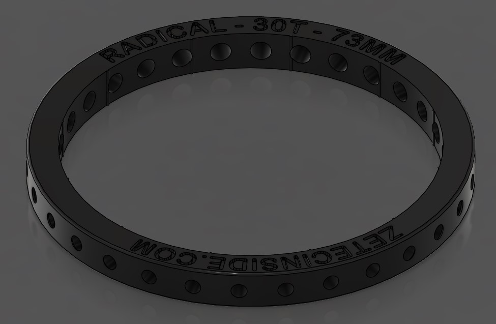
I've also designed a 30 dowel 73mm speed sensor ring for the car, which is away for printing.
28Feb
Front wing drop plates replaced
The pair of shorter (and cheaper to manufacture) front wing drop plates have arrived, so I quickly set about fitting them. These are 40mm shorter, which will move the front wing rearwards 40mm and reduce the downforce a small amount due to the change in leverage. They dont have the seven wing flap adjuster holes in them any more, since the shorter upper elements no longer reach or attach to them. Everything fits nicely together, and I'll get the wing back on the car for some more static load/deflection tests. As I am still waiting for the seat to come back from Triple M, I cant drive the car yet, and with the first event some 7 weeks away I've still time to get everything ready. I sold the Simpson Hybrid FHR/HANS this week which has raised some money towards the cost of purchasing the new dash.I'm currently helping rewire a Radical race car, which came with a DTA S100 ECU, and loom. The loom was from a car with a Zetec engine, and the Radical has a Busa 1300 Gen2 engine, so its simply a case of changing the connections, and making some new sections to join back to the ECU. The BUSA engine has COP's so I've made a loom to allow all four COPs to be fired individually. This weekends task is conencting the hall effect (3 wire) cam sensor to the ECU, so it can fire the COPs and the Injectors. So far the ecu is connected up to the Throttle Position Sensor, Coil on Plugs (COPs), Injectors, water temperature sensor, and the crank sensor. We've powered up the ECU and performed the COP test, and everything looks good so far.
I've also been doing some aero work for the current BSC Champion; Chris Jones was looking to improve the cooling for the Force TA, so we scanned in the side pods using an iPhone, and I have modelled the contours in to Fusion, and created a bespoke louvre panel, which Chris has printed and attached to the car. It looks pretty good, the fit is great, considering how rough the scan was from the iPhone. I'm sure it will make a big difference, and Chris will continue to run rings round all the other competitors in this years championship. (There are only 12 drivers registered presently! and thats with two new drivers entered).
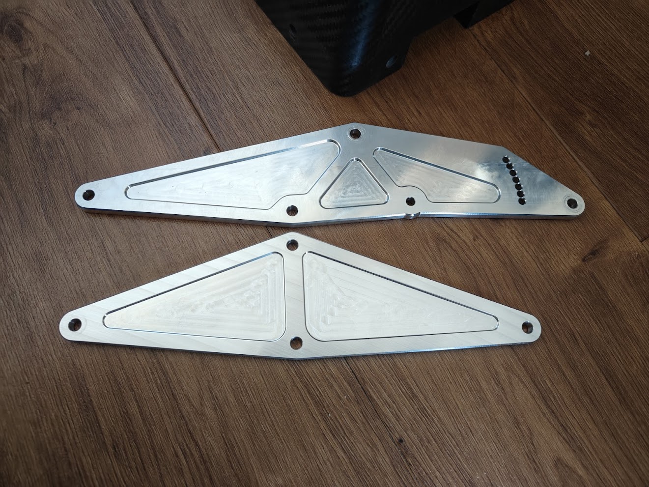
The shorter drop plate vs the longer one.
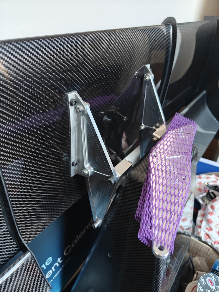
The shorter drop plates fitted to the wing assembly.
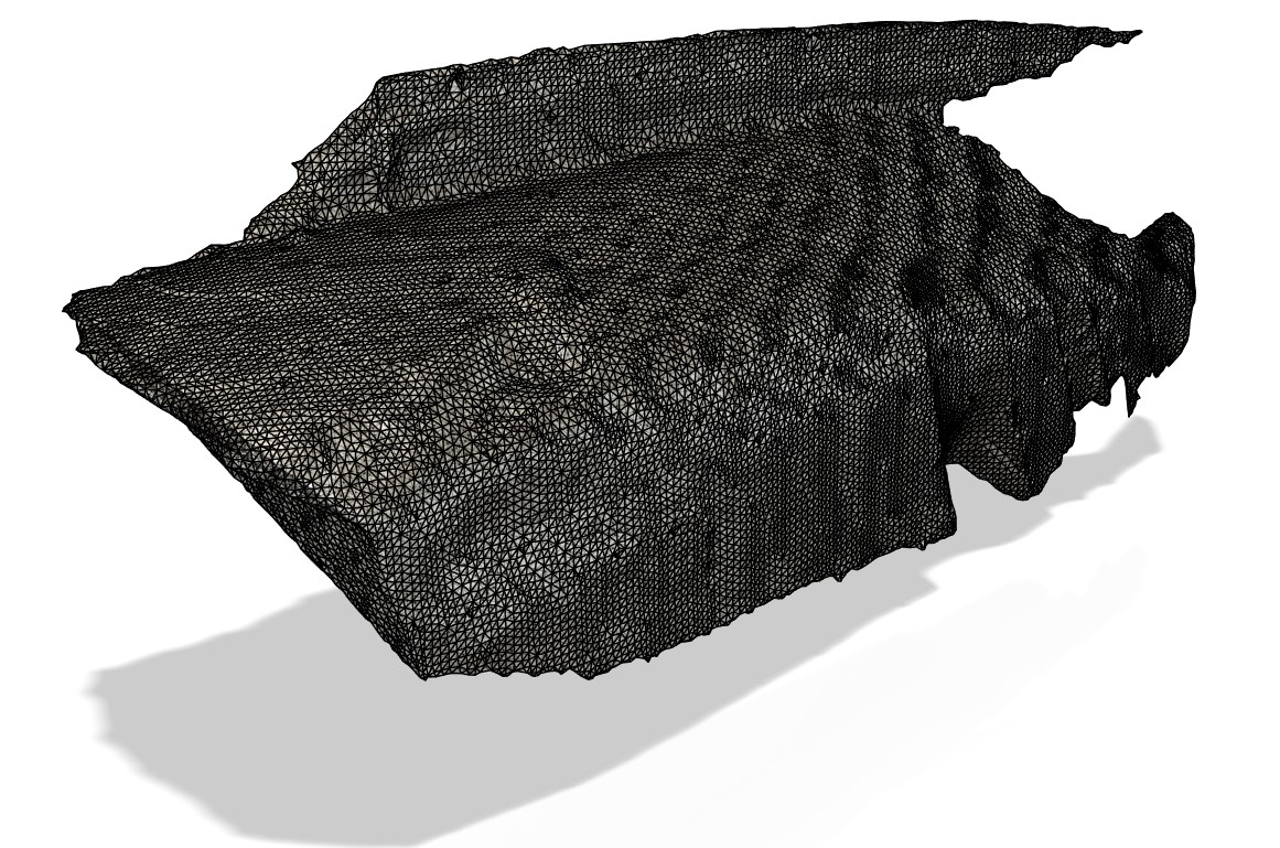
The iPhone scan of the Force TA side pod, imported in to Fusion. As you can see, the quality isnt that great, the surface is very rough. I used the form editor in Fusion to build a smooth surface over the side pod. It took many, many hours of modelling, but the end result should work, as long as it doesnt affect the laminar flow too much.
19Feb
Steering wheel and HANS
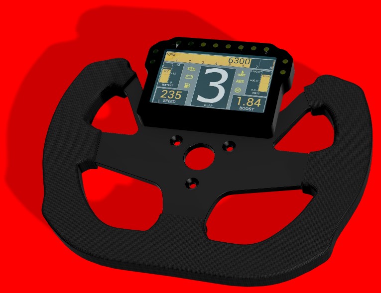
I've been trying to buy an OMP 27/C steering wheel, several companies claim to have them in stock, but when I ordered they came back with 'Long delays' and then 'No longer manufactured'. So I've gone for a Sparco F-10A from Demon Tweeks, which is a D shaped wheel (and is legal for Motorsport use) and I'm looking at changing from the Dash4Pro to a Plex SDM-330, which I'm hoping will fit on the wheel. I've modelled the wheel and dash in Fusion and a quick render shows it will look like this. Dave Gemzoe of Gemzoe Motorsport is going to supply the dash, which is on back order, and Dave will provide tech support if I have any issues with the CAN programmingI've just replaced the Hybrid Simpson FHR with a more common HANS FHR, at 30° and medium, which was supplied by Nicky Grist Motorsport. It fits me well, and the helmet already has HANS posts fitted, which the clips on the HANS FHR fit perfectly. The Simpson hybrid is far more comfortable to wear, but in the crash at Mallory was seen to rotate on my shoulders and although I suffered no neck strain, it didnt really look like it did what it was meant to do, so I'm going to sell it.
18Feb
Sustainable fuels
Exciting news from Sunoco, they are working on a range of Sustainable fuels for 2026, and they will include more oxygen than the current blends, which will mean even more power for the EcoBoost from next year. Read about it in their latest Crude News :D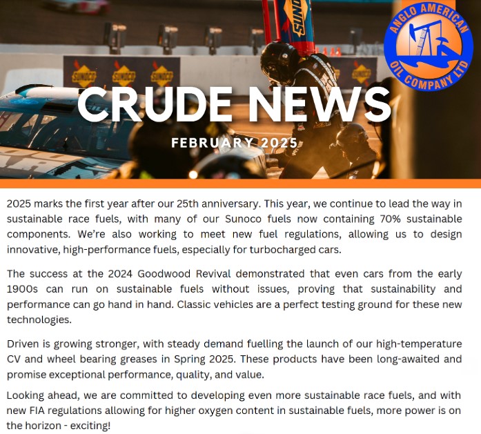
10Feb
Beccy lives
The XR2 is now road legal and track ready. And owner Simon Smail took it to Knockhill on Saturday for its first drive in ten years! Would you believe it's 10 years since I sold her? She looks and sounds brilliant. Running a 1600 EcoBoost with 240bhp (1bar) she easily spins the wheels in fifth gear on the greasy circuit, but Simon said he used 50 litres of fuel with no issues all day.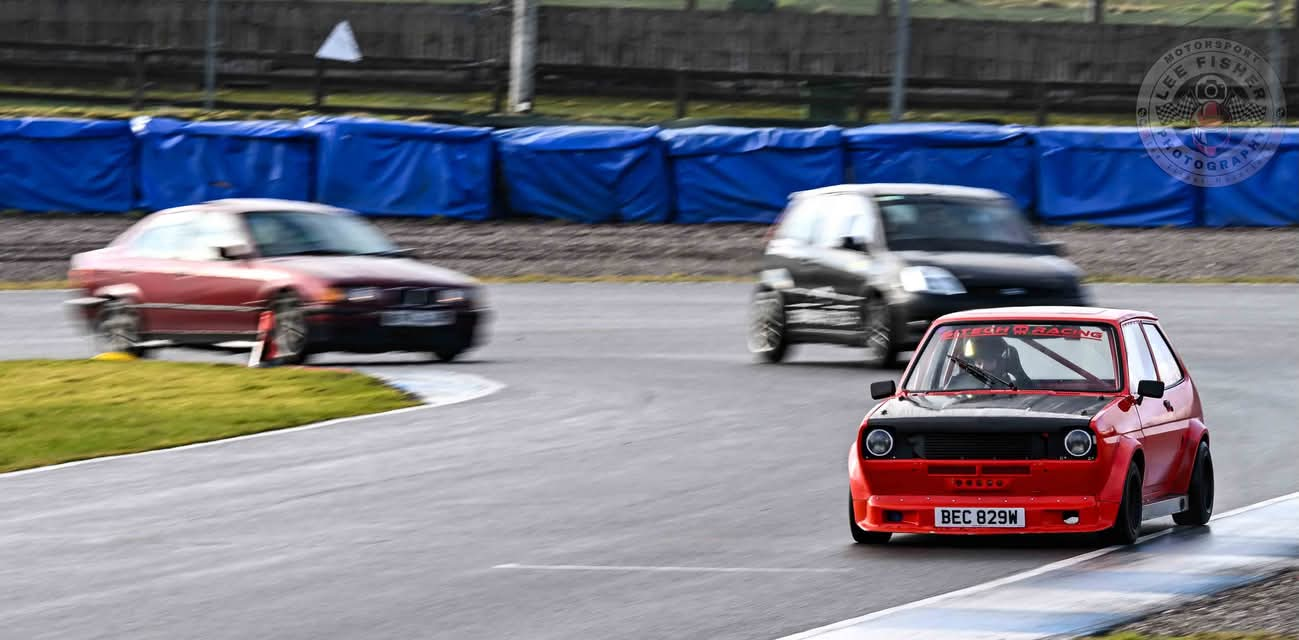
30Jan
Milling
The front wing drop plates are now being milled, so I should have them back in a few weeks time. I've now entered both the Javelin Sprints at Blyton in April and May and the Cadwell sprint in June, so thats something to look forwards to. I'm still waiting for the seat to be covered, by Triple M, and I hear they're very busy so I'm just going to have to be patient.27Jan
Blender progress
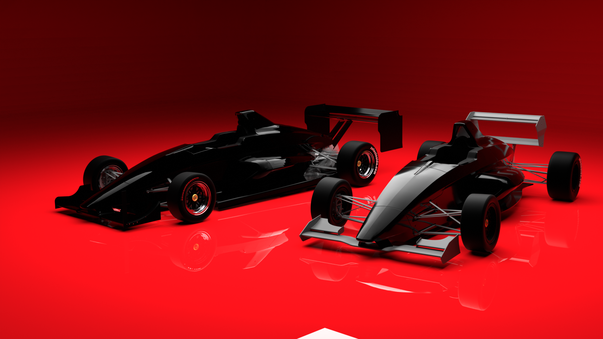
The results from Blender are improving. So much so, I've replaced the masthead on the website with a new picture.Click on the picture below to see the full size version.
22Jan
Front wing fitted and load tested
Over the weekend I fitted the front crash box and wing, using the new drop plates and drop plate supports, which are designed to be safer in the event of another frontal impact. The Playskool support plate prevented the crash box from crushing, so the new design will collapse more easily and the crash box should then absorb the energy, rather than the driver. Believe me, a dead stop at 30mph hurts! A lot.I measured the wing angle of the front wing on the Playskool bracket, at 2.5 degrees. This isnt the true angle, as the phone was just resting on the wing, and my garage floor isnt level, nor is the car sat on the Pirelli or Avon tyres it usually runs. But it was a good reference angle to work from. I then placed a 22kg load on the end of the wing, and measured the displacement.
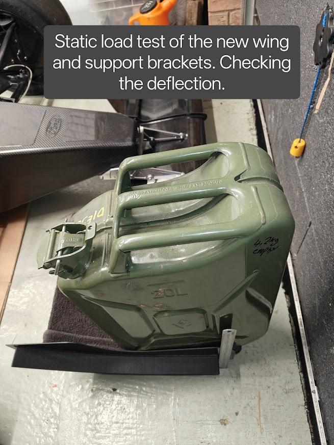
22Kg placed on the end of the wing.
Swapping over to the replacement brackets, which allow for adjustment of the main wing angle, using the phone I measured a 3 degree sweep, which means I can go from 0 to 3 degrees compared to the previous bracket, which was fixed and non adjustable. I then set the angle at 2 degrees, to increase the AOA of the main element, to increase the downforce it creates (lowering the leading edge increases the AOA). I then repeated the load test with the same 22kg load, and the wing deflects approx 2mm further with the adjustable brackets. Which I can understand, as I have taken 400 grammes of material out, and there are now two brackets in place of one large one. I think thats acceptable.
I designed a pair of shorter front wing drop plates, which will bring the front wing back by 40mm, and have a thicker centre section (up from 3mm to 4mm). These will put the stiffness back in to the front wing mounts, and I'm expecting them back in 4 to 5 weeks time. I will then repeat the load test to measure the deflection.
By reducing the distance of the front wing to the front axle, I will be losing a small amount of downforce, since the leverage will be reduced. But I can counteract that with the adjustable main wing angle, so I'm not concerned about the change.
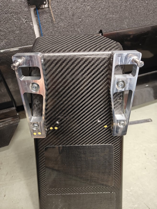
The adjustable support plates I designed.
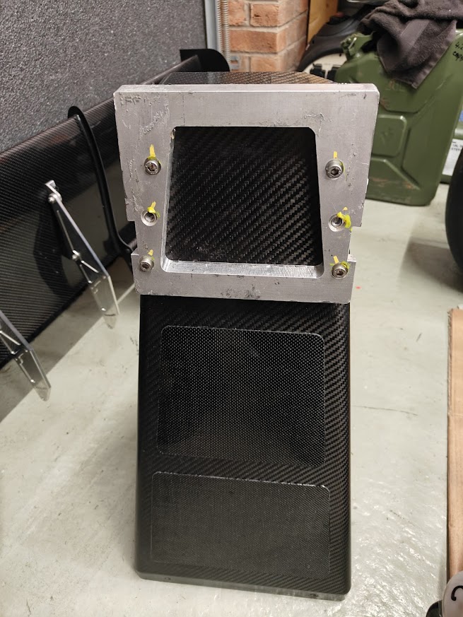
The Playskool plate
I am now designing a pair of deflectors to sit ahead and inboard of the front wheels, to reduce tyre squirt. These will be 3D printed, and attached to the front wing end plates. Tyre squirt plays havoc with the air flow through the floor and the diffuser, so by removing the turbulent air, I am expecting to see further gains in the downforce produced by the floor.
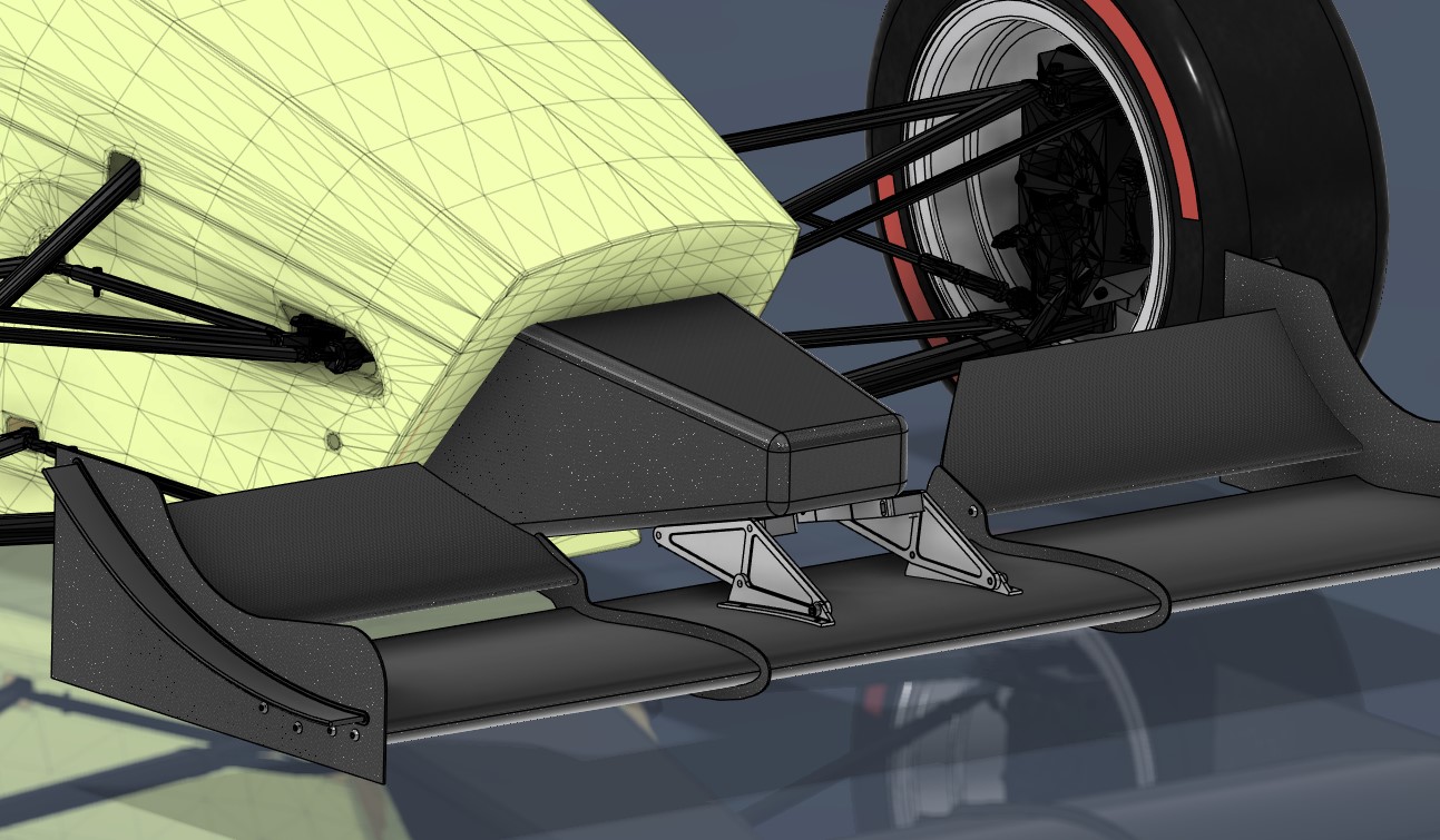
My Fusion CAD model showing the shorter drop plates fitted.
The Digital Twin model of the car is now pretty much complete. I took measurements at the weekend of the position of the floor to the bodywork and wings, and edited the positions of the parts in the model, so for CFD this is about as close to the actual car as I can get it.
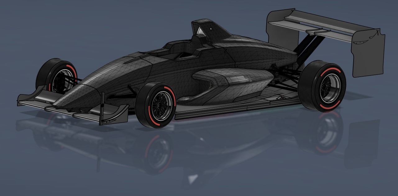
The digital twin of the Mygale EcoBoost.
8Jan
Javelin sprint entered
I've entered the Blyton April 13th round of the Javelin sprint series, which will be the first outing this year. Its great value for money, with at least six runs, free photography, and class awards. I'm in T1 for single seaters over 600bhp/tonne.6Jan
Extraction video
This video explains how I managed to extract the cad data from Forza Motorsport 7 re-pack, and import it into Fusion.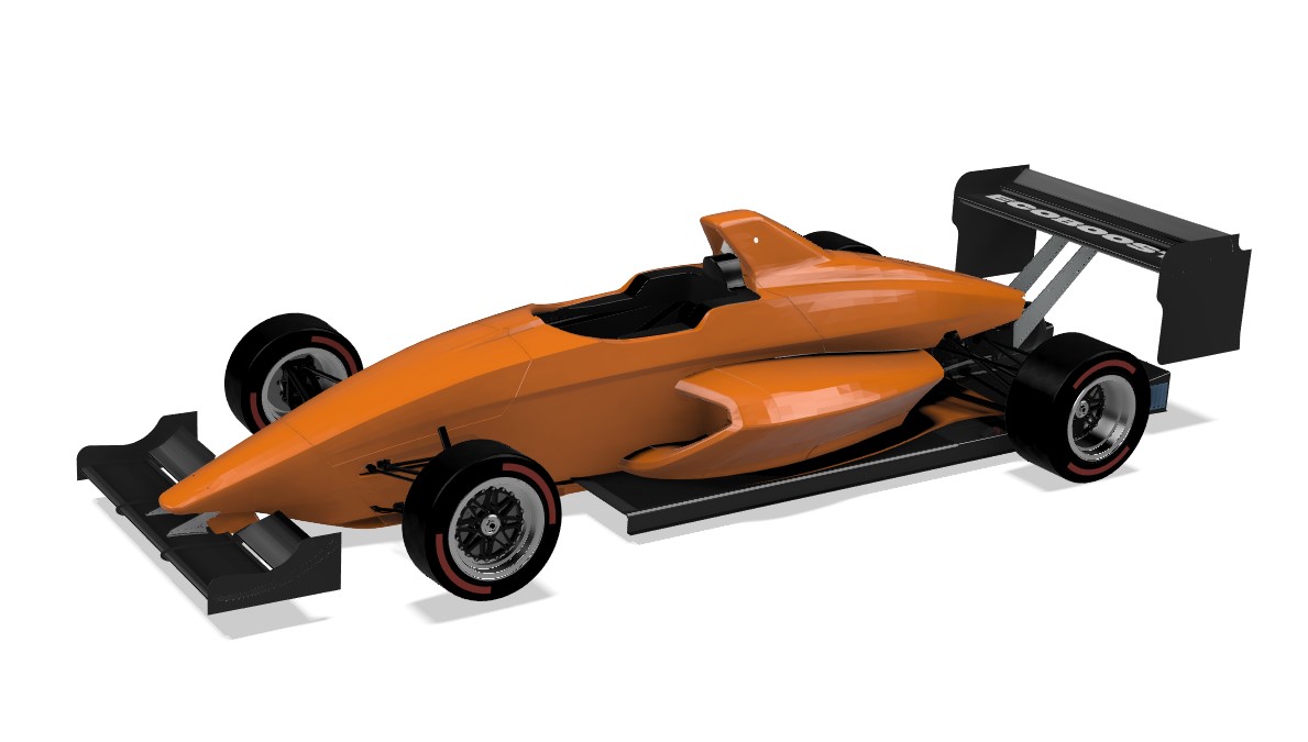
This is the chassis built up with the diffuser, floor, and the DJ Aero, and the wheels I've designed in Fusion. Looks great in Papaya orange :D
29Dec
FF200 model located!!!
For a very long time, I've wanted to obtain the CAD model of the car from Mygale. Or Ford, but neither party were able (or willing) to help. And then 10 years ago, Forza Motorsport featured the car, in glorious detail, and I knew there was going to be a possibility somehow of finding that model, and seeing if there was a way of using it in Fusion. To cut a long story short, I managed to obtain the FOR_FormulaFord_13.carbin file from Forza Motorsport 7, and using 3DsimED, I have opened the file, and exported the FF200 model in to FBX format (as a single file and as all the individual components that make the model). This allows me to import the components that the car is made up from, into Fusion, where, I can convert the Mesh bodies to Solid, and use them in my models.The next step was to try and produce some renders of the bodywork, so I downloaded Blender, and tried to import the FBX files, but Blender said it couldnt open the files as they were in 6100 format. No problem. Opening the .FBX files in Windows 10, using 3D Paint, allows the files to be saved in GLTF Binary format, which Blender then imports.
The results are amazing. I just wish I had the models for Henry's Dissertation that he completed this year, his CFD results would have been even more accurate had we got the CAD model of the car.
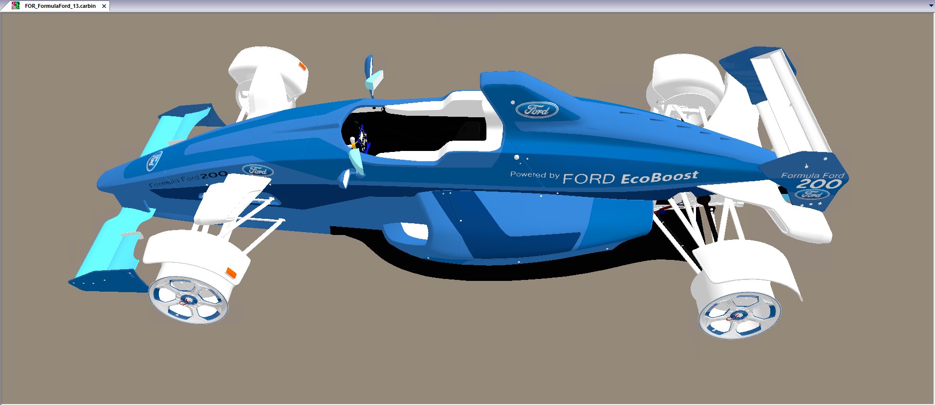
The Forza model open in 3DsimED
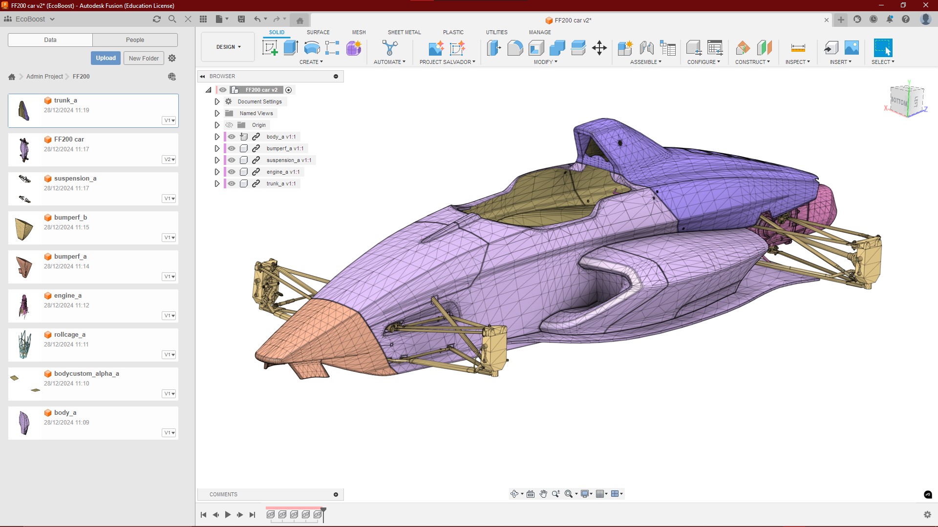
The FBX export from 3DSimED, imported in to Fusion.
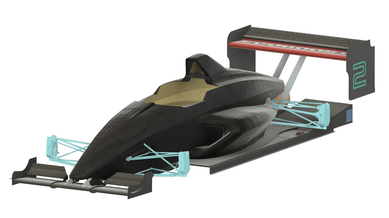
My Fusion 360 aero model with the FF200 body work.
25Dec
Happy Christmas
It's that time of year again, wishing all my friends and followers a very happy Christmas
22Dec
Front wing drop plate support brackets have arrived
Weighing in at just 121g each, these save almost 400grammes over the plate that was bolted to the underside of the crash box. Here's a video showing the design, prototype and production of them both.19Dec
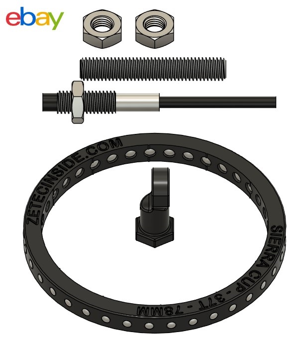
Sierra diff-housing wheel speed sensor kits now listed
The new batch of printed sensor rings for the sierra push-fit output cup have just arrived so the listing for the complete sensor kits is now live on ebay. https://www.ebay.co.uk/itm/156590510729I collected the painted nosecone and bonnet at the weekend from Faircharm Restorations, and they look fantastic in the gloss black. Thanks Shane for another excellent job.
9Dec
Sierra diff-housing wheel speed sensor kits
Just waiting for a batch of sensor rings to arrive, and then these wheel speed sensor kits will be on ebay for purchase. Supplied with all the parts you need to add wheel speed sensors to a kit/space framed car running the Sierra diff-housing (eg Westfield/Caterham/MK Indy etc).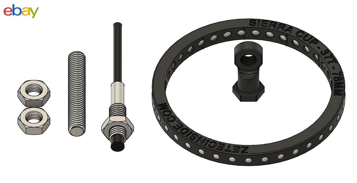
5Dec
Printed Fiesta rings
The pair of 91mm sensor rings for a Ford Fiesta arrived this morning. These are SLS printed, with 24 dowels.
They are built up with the steel dowels and are now in the post to another new customer.

4Dec
Printed Sierra rings and sensor brackets
I've just had another set of Sierra 78mm sensor rings delivered, with a set of M8x1.0mm sensor brackets. The brackets are printed with the 1.0mm thread to allow the sensor to be screwed in, using just one of the pair of M8x1.0 nuts to lock it in place. The other version of the bracket allows the sensor to be inserted and held in position with two M8x1.0 nuts. Both designs are available for £10 for a pair. The sensor rings remain at £25 each. The SLS printing service I use remains to be expensive, but the quality and details achieved with SLS are far greater than anything that can be printed at home.

Offset M8 sensor bracket for the Ford Sierra diff housing

M8 sensor bracket for the Ford Sierra diff housing
2Dec
Trip over to TripleM for a seat fitting
It was good to get back behind the wheel of the van with the trailer in tow again, for a trip to TripleM Motorsport near RAF Scampton in Lincolnshire. The A46 and A15 were busy, but the trip only took 1.25 hours and I was there for the 9:30 start.

With the car unloaded and pushed into the garage, Alan and Nick set about making cardboard templates, to block in the space frame at the sides. This is essential to provide the seat with anchors to prevent it from moving.

We then tried the Medium seat kit, but the bag didnt have a great enough volume of beads to provide me with the protection we were looking for. A swap to the more expensive large kit, (which is the same bag but with 50% more beads) provided a much greater volume, and once we were happy with the distribution, the bag is removed and the 1.5 litres of chemical resin are added, and after 15 minutes of break making, the beads were all evenly coated with the resin. Alan and Nick then added the requisite amount of cold water, which starts the chemical reaction to harden the resin. This is quickly spread around the beads, with some more needing, and then we had 20 minutes to put the bag back in to the car, push the beads where they were required, and I sat in the car, wiggled my bum around to get comfortable, and then the bag is pushed in to shape by hand, and a vacuum applied to the bag to prevent anything from moving.

I then remained in the car for a further 35 minutes, which kept the bag from changing shape while the resin cured and hardened. Once that time had passed I hopped out, and Alan and Nick removed the seat, and started trimming it to shape.

The thickness of the sides were reduced, to allow it to be removed from the car more easily, whilst retaining the shape of the space frame, which helps keep the seat locked in to position.
Belt holes were then cut, and after another hour or so of trimming, the seat was refitted with the belts pulled through, and I sat in it, did the belts up to prove everything was OK, and hopped out again. The seat was then removed and will be covered in Nomex flame retardent material, which will keep all the beads in situ, and strengthen the core of the seat.

From start to finish the job took around 7.5 hours to complete. The seat fits me perfectly, and should keep me in situ should I hit anything substantial again. I will be changing from the Hybrid HANS to conventional HANS as I am very aware how much the HANS moved in the crash. It just rolled off my shoulders as I slid forwards, and I'm not prepared to risk that happening again.

I also collected the new Pirelli Ultrasofts from Alan, and these will be fitted to a new pair of rims, and kept for the cold weather events.
Here is a short to the seat fitting process, filmed yesterday at the workshop.
https://youtube.com/shorts/pD1gl-ocZC0?feature=share

